Your coupon for will be reflected when you check out!
✖
Your coupon for
✖
Hello!
You're visiting the PartSelect site in U.S.
Would you like to shop on the Canadian site?
Stay on this site
Go to Canadian site
✖
Model Number Locations
1Select Category Type
Select Category Type
2Select Product Type
Select Product Type
3Select {MODEL} Type
Select {MODEL} Type
Sample Model Number Tags
Model numbers can be made up of numbers (1005400, for example) or a combination of letters and numbers (LAT1000AAE). The model number will most likely appear on either a paper sticker or a metal plate. Your appliance's model number tag may look similar to the sample model number tags shown here (model number highlighted in yellow):
Model has been saved to My Models. If you're not signed in, your lists are available on this device and will expire within 30 days.
Model has been saved to My Models.
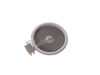
This is a grease filter, and it works with your range/stove/oven. This part is chrome-colored and measures 16.5 inches long by 9 inches wide. It is made of metal and is intended for use with downdraft...
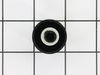
This is the replacement surface burner switch for your range. It measures approximately 1.5 inches by 1.5 inches, with a shaft that is approximately 1 inch long. The surface burner switch turns the su...
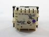
Introducing the Fan Control Switch from Whirlpool, a top-tiering brand known for its unwavering commitment to quality. This is a genuine OEM part, intricately crafted to function with optimal efficien...
We're sorry, but our Q&A experts are temporarily unavailable.
Please check back later if you still haven't found the answer you need.
6 questions answered by our experts.
Sort by:
< Prev
1
2
Next >
Search filter:
Clear Filter
Your search term must have 3 or more characters.
Keep searches simple. Use keywords, e.g. "leaking", "pump", "broken" or "fit".
Sorry, we couldn't find any existing answers that matched.Try using some different or simpler keywords, or submit your new question by using the "Ask a Question" button above!
Frank
May 27, 2022
One of the big elements stays on high even if you turn it to low
For model number JED8430ADB
Hello Frank, Thank you for the question. This is an indication the switch that controls the element is faulty and will need to be replaced. If you need help placing an order, customer service is open 7 days a week. Please feel free to give us a call. We look forward to hearing from you!
push button switch for the fan to turn on and off will not pop up any more
For model number JED8430ADB
Hello Jack, thank you for the query. According to our research, you may need to replace the fan control switch, part number PS11744308, to fix the issue. We hope this solves your problem!
Hi Kevin, thank you for contacting us. Based on our research, a side clearance of at least 6 inches is recommended for optimum ventilation. We hope this information helps!
1 person found this helpful.
Was this helpful?
Thank you for voting!
Annette
March 17, 2024
The front right burner will not turn off on this stovetop
For model number JED8430ADB
Hi Annette, thank you for reaching out. Based on our understanding, the issue could be with the dual burner infinite switch, part number PS2003583. It turns the surface element on and off and controls how much heat the element produces. You may need to replace it to fix the issue. We hope this solves your problem!
Remove Ceran Galss top by removing hex screws below the rim. Also remove the two opposing screws in the center of the downdraft opening. Ceran top comes off easily now. The instructions with the new switch were very poorly written, so here is how I got the new switch to work: Attach the black wire(s) from the old switch (termi
... Read morenal 2) to the new switch terminal P1. Also attach the jumper cable to P1 and "jump" it to S1.
Attach the orange wire (old switch terminal 5) to S2 Attach the yellow wire (old switch terminal 4) to 4a Attach the tan/(white?) wire (old switch terminal 3) to terminal 4 on the new switch Attach the single red wire from the right front element to terminal 2 on the new switch. Attach the 'compound' red wires (the ones that come from the left rear/outlet connection and is also attached to the right rear switch) to terminal P2 on the new switch. There is no need to seperate the compound red wires as the instructions might lead you to believe. Good Luck
The repair itself was very easy. “How to connect” was very hard to get.
To get access to the switch, unscrew 2 screws from each side of front panel and then 4 screws from the bottom of it (open the door first). Have a box or a small table about 30” high to use it as support for the front panel.
The end result
... Read more(colors for the Right Front- R.F.- burner) : Old label -> New label
1. Double RED: N -> P2 (incoming power, Line 1) 2. Single RED: N -> 2 (to Inner AND Outer heating elements common wire) 3. Single BLK: L1 -> P1 (incoming power, Line 2) 4. Single TAN: H1 -> 4 (to the Inner heating element) 5. Single YEL: H2-> 4a (to the Inner heating element) 6. Single BLK: P -> S2 (to the R.F. indicator control light) 7. Attach jumper black wire (included with new switch) from P1 (P1 has two connectors close together) to S1.
This was a range top. i removed the 12 hex machine scews holding on the top, then removed the two star screws holding the old switch. there were fore wire that had fitted on tabs. Hooked them to the new swtch and reassembeld. Easy repair since i could lift the unit out without disconnecting main cables. Replacement range would have
... Read morebeen oveer $1000. Psrt was under $40 and delivered in a matter of days.


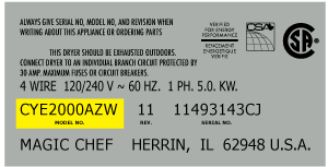


 Diagram and Parts List for Jenn-Air Cooktop")