Your coupon for will be reflected when you check out!
✖
Your coupon for
✖
Hello!
You're visiting the PartSelect site in U.S.
Would you like to shop on the Canadian site?
Stay on this site
Go to Canadian site
✖
Model Number Locations
1Select Category Type
Select Category Type
2Select Product Type
Select Product Type
3Select {MODEL} Type
Select {MODEL} Type
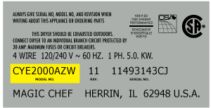
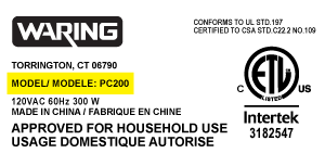
Sample Model Number Tags
Model numbers can be made up of numbers (1005400, for example) or a combination of letters and numbers (LAT1000AAE). The model number will most likely appear on either a paper sticker or a metal plate. Your appliance's model number tag may look similar to the sample model number tags shown here (model number highlighted in yellow):
Model has been saved to My Models. If you're not signed in, your lists are available on this device and will expire within 30 days.
Model has been saved to My Models.
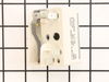
The 8-inch surface element switch is also known as an infinite heat switch, and is a part for your range. It controls the large surface element. It will turn the element on and off, and allow you to c...
$41.95
In Stock
Order now and your part arrives in 2-3 business days!
The drip bowl on your range is designed to catch any spills that may occur when cooking. This drip bowl is chrome in color and is 6 inches in diameter. The chrome drip bowl is intended for use with ro...
$19.95
In Stock
Order now and your part arrives in 2-3 business days!
Drip bowls are located under the heating elements and catch grease and spills that come from cooking on your stove top. If your drip bowl is damaged or rusted, it could allow grease to drip inside you...
$23.95
In Stock
Order now and your part arrives in 2-3 business days!
This 40-Watt light bulb is sold individually and is a genuine OEM replacement option for your home appliances. It is specially designed to withstand extreme temperatures, so this bulb is compatible wi...
$19.10
In Stock
Order now and your part arrives in 2-3 business days!
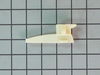
The metallic clip, or also known as a broil element support, is for a oven element on a range. This part holds the broil element in place on top of the oven. If your support clip is broken then this r...
$16.95
In Stock
Order now and your part arrives in 2-3 business days!
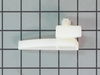
It is possible that your oven is cold because of a fault in the temperature sensor. The temperature sensor regulates oven temperature in modern ranges, like a thermostat. It is on the back wall near t...
$37.95
In Stock
Order now and your part arrives in 2-3 business days!
This part is a replacement lens for your oven or range. The lens is red in color, and when the elements are turned on, the light behind the lens will turn on to inform the user that the element is, in...
$13.95
In Stock
Order now and your part arrives in 2-3 business days!
Introducing the Genuine Replacement Drawer Glide specifically designed for General Electric Range/stove/ovens. This is a crucial element that supports your broil or storage drawer, effortlessly allowi...
$13.95
In Stock
Order now and your part arrives in 2-3 business days!
The GE brand is known for its high-quality appliance parts and this OEM Indicator Light for Ranges is no exception. This small yet significant piece lights up to signal when the oven or surface burner...
$23.95
In Stock
Order now and your part arrives in 2-3 business days!
Questions And Answers for JCAP750WM2WW
Ask our experts a question about this model and we'll get back to you as soon as possible!
1 question answered by our experts.
Sort by:
< Prev
1
Next >
Search filter:
Clear Filter
Your search term must have 3 or more characters.
Keep searches simple. Use keywords, e.g. "leaking", "pump", "broken" or "fit".
Sorry, we couldn't find any existing answers that matched.Try using some different or simpler keywords, or submit your new question by using the "Ask a Question" button above!
Barb
November 27, 2023
I removed burner to clean drip pan. Burner will not plug in correctly and burner won't sit flat.
For model number JCAP750WM2WW
Hello Barb, thank you for your inquiry. Try moving them around and see if your burners are not different sizes. There is also a notch in the circle part that must line up, so they go down and stay down. We hope this information is useful!
Was this helpful?
Thank you for voting!
< Prev
1
Next >
✖
Ask a Question
Ask our experts a question on this model and we'll respond as soon as we can.
This repair is EASY if you know how to use an ohm meter. If not, seek help for this step.
SYMPTOM: The oven (JKP27WOP3WG or JKP27WP3WG and many ovens like it ) was not getting hot enough. Verifying the cooking temperature with an typical oven thermometer, I was able to determine that the oven was cooking temperature was
... Read more about 150 degrees to low.
FAILURE POINTS: There are two logical failure points (1) The oven sensor ( WB21X5301 about $75), or the (2) the controller board (PS238233 about $252). In my case it was the controller board. When replaced the oven worked beautifully.
REPAIR: As with any repair, you MUST DISCONNECT POWER TO THE UNIT BEFORE SERVICING!!!
Pull oven from the wall: - Disconnect power by flipping the circuit breaker to the OFF position. - Remove the top flange / cowling from the top of the oven (it just pulls off) - Remove two screws under the top flange / cowling - The whole unit easily slides out, but it is highly recommended that you use two people to place the oven on the floor.
As a diagnostic between these two parts, if the oven sensors measure approximately 1.1K ohms of resistance at room temperature, then it is probably not the sensor. The oven sensor wires are connected to two white wires that run up to the controller board. You need to disconnect the oven sensor to make the measurement. You may either completely remove the oven sensor by cutting the wire (be sure to allow yourself enough slack so that they may be safely reconnected) where it connects to the white wires, OR, (preferred method) if leaving the oven sensor partially installed, - Remove the top sheet metal cover (10 screws) - Remove the service connect cover (2 screws - this is where the main Power cord comes into the unit) - Disconnect the white wires from the controller board (this connector which also includes other circuits is on the left side when looking at the controller board). - Remove two screws from oven sensor but just let in dangle down so that you can put the sensor in the ice water / boiling water.
Measure the resistance under the following conditions. Your ohm meter should read APPROXIMATELY... - 1.02K ohms in ice water - 1.09K ohms at room temperature - 1.36K ohms in boiling water. If you get approximately these readings, then it is NOT the oven sensor. If that checks out then re-install the sensor AND the connector.
If it is NOT the sensor, replace the controller board. - Take a moment to write down the color of the wire to the LETTERING (N, L, G, C / COM,,,) on the controller board. The connectors are in different locations on the new controller board so the wire color to the letter designation is significant. - Carefully remove the wires one at a time - VERY carefully remove the keypad ribbon cable from the right side of the controller board. -- The ribbon cable will disconnect by releasing some little pressure clips on the side of the connector. - Remove the controller board (4 screws) - Install new controller board (4 screws) - VERY carefully connect the keypad ribbon cable on the right side. -- Make sure that the connector is in the OPEN position first, then, -- Slide in the cable ensuring that all parts of the ribbon made it into the connector, then -- Press down on the connector locking tabs. - Reconnect each wire to the correctly lettering on the board. -- Again, the connectors MAY BE in a different order on the replacement controller board. Match color to letter. - Reconnect the (5 wire?) connector that includes the white oven sensor wires. - Make sure everything looks normal, (i.e. no wires are pinched, remove tools from top of oven area, etc.) - Re-install top cover. - Re-install service connect cover.
You can test the unit while it is out of the cabinet, - Make SURE that all sheet metal covers are in place. - Flip power breaker to "On". - Test that oven gets to the desired temp.
Remove nobs from both switches. Pull out the range (the hardest part). REMOVE THE POWER PLUG FROM THE WALL Remove 7 screws with nut driver and take off upper back panel. Remove 2 phillips screws from front, they hold the switch brackets. The new switches don't fit in the bracket so discard the bracket keeping the
... Read morescrews. Removing 1 wire at a time from the old switch transfer to the new noting the letter/number ie "H1 P1" combos they are all there just not in the same places on the new switch. When wiring is complete, using the bracket ,screws from the front screw on the switches. Replace the back panel with 7 screws. In my case the old nobs did not fit the shafts of the new switches. I found some at the local hardware store. I bought 4 for $0.29 each! I expect to be replacing the other burner switches shortly.
unplugged unit pulled it away from wall took off the backplates traced wire to plug replaced with part ordered very smooth operation. the most impressive thing to me was i ordered part on computer and it was at my door in 30 hours awesome.


 – Part Number: 40A15")